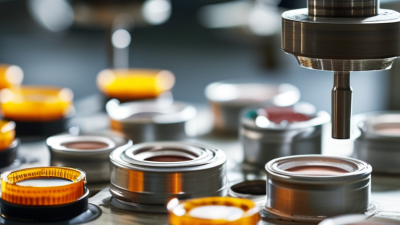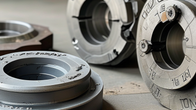
A Cap Mold is the precision tool that shapes plastic closures for bottles, jars, and containers. It defines the cap’s threads, sealing surface, ribs, tamper band, and visible finish. Behind a simple bottle cap lies careful engineering.
During production, heated plastic enters the mold cavity under controlled pressure. The mold then cools the material until it becomes stable enough to eject. Cooling channels, venting paths, steel selection, and cavity alignment all affect the final result. Small errors spread. They may appear as uneven threads, flash, weak seals, or difficult ejection.
Understanding how a Cap Mold works helps manufacturers make better choices before production begins. Mold designers consider resin behavior, shrinkage, cycle time, wall thickness, and the required closure performance. Operators also monitor temperature, pressure, lubrication, and wear during regular runs. The details matter.
A reliable mold should produce consistent dimensions across thousands of cycles. However, no design is perfect in every application. A mold optimized for speed may require more careful cooling control. A highly detailed cap may increase tooling cost and maintenance demands. This balance deserves honest evaluation.
This guide explains the main components of a cap mold and follows the forming process step by step. It also examines common defects, maintenance concerns, and practical design decisions. The goal is clear: connect technical principles with the small manufacturing details that determine whether a cap performs properly.
What Is a Cap Mold and How Does It Work?
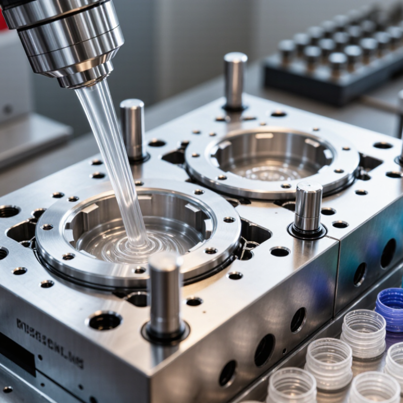
A cap mold is a precision tool used to form plastic closures for bottles, jars, and containers. It contains shaped cavities that define the cap’s outer surface, threads, tamper-evident band, and sealing features. During molding, heated plastic enters the cavity and cools around a central core. The mold then opens, and ejector components release the finished closure.
Its role in closure manufacturing is more important than appearance alone. A well-designed mold helps control wall thickness, thread accuracy, sealing pressure, and production speed. These details affect whether a cap opens smoothly and protects the contents reliably. Cooling channels remove heat evenly, reducing warping and shrinkage. Small errors can create loose threads, weak bands, or uneven seals. In my experience, technicians often check sample closures under magnification and measure them with gauges. A perfect-looking cap may still fail a functional test. Mold design also needs to match the material, equipment, and expected output. That choice is not always simple.
Tips: Check cooling balance before increasing production speed. Inspect thread dimensions regularly. Watch for flash near the sealing edge. Keep maintenance records, even when the mold appears stable. A minor cavity mark can become a repeated quality problem.
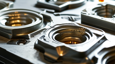
A cap mold forms a closure by shaping molten plastic inside a controlled steel cavity. The cavity creates the outside profile, including threads, ribs, and tamper features. The core forms the inside diameter and sealing surface. Together, they define wall thickness. Small alignment errors can create uneven threads.
The gate directs plastic into the cavity. Its location affects weld lines, filling pressure, and visible marks. A balanced multi-cavity layout helps each cavity receive similar flow. According to Grand View Research’s 2024 Injection Molded Plastics Market report, the global market reached an estimated USD 265 billion in 2023. That scale explains why repeatability matters, even in a small cap.
Cooling channels remove heat from both cavity and core. Technical guidance from the Society of Plastics Engineers indicates that cooling often consumes about half to two-thirds of an injection cycle. Channel distance, water temperature, and steel thickness all influence shrinkage. Ejector pins then push the cooled cap from the core. Their force must be distributed carefully; concentrated pressure can leave pin marks or distort the sealing lip. In practice, designers sometimes overfocus on cavity polish and undercheck cooling balance. That is a costly mistake. A cap may look perfect, yet fail torque or leakage testing after storage. Temperature mapping and dimensional checks reveal problems that visual inspection misses.
| Core Part | Primary Function | Typical Material | Typical Design Data | How It Works During Molding | Important Design Considerations |
|---|---|---|---|---|---|
| Cavity | Forms the outside surface, threads, sealing features, and external geometry of the cap. | Pre-hardened or hardened tool steel; corrosion-resistant steel may be selected for abrasive or corrosive environments. | Cavity count commonly ranges from 1 to 96 or more in high-volume cap production. Surface finish is selected according to the required appearance and release behavior. | The cavity half closes around the core. Molten polymer fills the space between them and cools against the cavity wall. | Uniform wall thickness, correct shrinkage allowance, adequate draft, thread accuracy, and balanced filling are essential for consistent dimensions. |
| Core | Creates the inside diameter, internal thread form, closure space, and other internal features. | Tool steel, often hardened or coated where wear resistance is required. | Core diameter is determined by the cap’s internal dimensions and material shrinkage. Threaded caps may use unscrewing, collapsible, or stripper-core mechanisms. | The core occupies the internal volume of the cap while plastic flows around it. After cooling, the molding system separates the part from the core. | Thread geometry, venting, core alignment, demolding torque, and cooling uniformity affect sealing performance and cycle reliability. |
| Gate | Controls the entry of molten plastic from the runner into each cavity. | Machined tool steel, sometimes with a hardened insert at high-wear locations. | Common gate types include hot-tip, valve, edge, and tunnel gates. Gate dimensions depend on resin viscosity, cap weight, wall thickness, and required filling time. | The gate meters the flow and freezes at a controlled point as the part cools. The gate location determines the visible vestige and filling pattern. | Gate balance, shear heating, pressure drop, vestige size, weld-line position, and prevention of short shots or flash must be evaluated. |
| Runner System | Transfers molten polymer from the sprue or hot manifold to the individual gates. | Tool steel for cold runners; heated steel components for hot-runner systems. | Cold runners create additional regrind or scrap, while hot runners can reduce runner waste and support multi-cavity balance. | The runner distributes polymer under pressure. In a balanced layout, each cavity receives material at approximately the same time and pressure. | Runner balance, heat control, residence time, pressure loss, and material degradation are key factors in stable production. |
| Cooling Channels | Remove heat from the mold and solidify the cap before ejection. | Machined mold steel passages with water or another controlled heat-transfer fluid. | Cooling-channel diameter is often approximately 6–12 mm in many mold designs, but the final size depends on tool geometry, flow rate, pressure drop, and available space. | Temperature-controlled fluid circulates through passages near the cavity and core, carrying heat away from the polymer and mold steel. | Channel distance from the molding surface, circuit balance, turbulent flow, leakage prevention, and avoidance of hot spots influence cycle time and warpage. |
| Ejector System | Removes the cooled cap from the core without damaging threads, sealing surfaces, or cosmetic areas. | Hardened tool steel ejector pins, sleeves, stripper rings, or specialized release mechanisms. | Ejection force depends on shrinkage, contact area, draft, surface finish, resin, and mold temperature. Ejectors are generally distributed to avoid localized deformation. | After the mold opens, pins, sleeves, or a stripper plate move the part away from the core. The system then retracts before the next mold closing cycle. | Balanced force, adequate stroke, pin marks, synchronization, lubrication, and prevention of part sticking are critical for reliable operation. |
| Vents | Allow trapped air and gases to escape as the cavity fills. | Precision-machined mold steel surfaces, vent inserts, or porous venting components. | Vent depth is resin- and process-dependent; it must be large enough for gas release but small enough to prevent flash. | Air exits through vents located near the end of fill, weld-line zones, or other areas where gas can become trapped. | Insufficient venting can cause burn marks, incomplete filling, weak weld lines, and unstable cavity pressure. |
| Mold Alignment System | Keeps the cavity and core accurately aligned during mold closing and injection. | Hardened guide pillars, guide bushes, locating rings, and precision alignment components. | Alignment accuracy must support the required part tolerances and prevent core-to-cavity interference. | The guide system engages before the molding surfaces meet, maintaining positional accuracy under clamping and injection loads. | Wear, contamination, insufficient lubrication, and excessive offset can cause flash, uneven wall thickness, or premature mold damage. |
A cap mold is a precision tool that shapes molten plastic into a finished cap. It contains cavities, cores, cooling channels, and an ejection system. From practical molding experience, small alignment errors can leave visible parting lines or uneven threads. The process sounds perfectly linear, but real production is less tidy.
Injection molding forms caps through four main process stages.
During mold closing, the machine clamps both mold halves under controlled pressure.
In the injection stage, heated plastic flows through the runner into each cavity. Pressure must remain stable to fill fine thread details and sealing surfaces.
Cooling then solidifies the cap while channels remove heat from the steel mold. Cooling too quickly may cause warping. Cooling too slowly may reduce production efficiency.
During ejection, pins or a stripping mechanism release the cap without damaging its threads. Operators inspect samples for flash, short shots, deformation, and inconsistent weight. Not every defect comes from the mold; material moisture and machine settings also matter.
Tips: Keep cooling channels clean and balanced. Check cavity vents regularly. Measure cap dimensions after cooling, not immediately after ejection. Record changes carefully, because a minor adjustment can affect torque and sealing performance. A practical warning: faster cycles are not always better. Stable molding usually produces more reliable caps, even when the cycle is slightly longer.
A cap mold is a precision tool that forms plastic closures through repeated molding cycles. Molten polymer enters each cavity, cools against steel surfaces, and exits as a finished cap. The mold also controls threads, tamper bands, wall thickness, and sealing features. Small dimensional errors can cause leaks or poor bottle fit.
Cavity count directly affects output. A 16-cavity mold produces 16 caps per shot, while a 96-cavity mold produces six times more.
At an 8-second cycle, 16 cavities can theoretically deliver 7,200 caps per hour. A 96-cavity system could reach 43,200 caps per hour.
At 20 seconds, those figures fall to 2,880 and 17,280 caps. These calculations exclude startup losses, maintenance, rejected parts, and material changes. The factory floor is less perfect.
Short cycles demand balanced filling and efficient cooling. Uneven temperature can create warpage, weak hinge areas, or inconsistent thread dimensions. High-cavity tooling also raises the cost of maintenance and process control.
One blocked gate can affect production across several cavities. According to PlasticsEurope’s Plastics—the Fast Facts 2023, global plastics production reached 400.3 million tonnes in 2022. Smithers’ packaging market forecast values global packaging at about $1.17 trillion in 2023, showing why reliable closure production matters.
Yet maximum cavity count is not always the best choice. A slower 16-cavity mold may deliver better consistency for specialized caps, while a 96-cavity mold suits stable, high-volume production. Reality needs checking.
A cap mold is a precision tool that shapes plastic closures during injection or compression molding. It uses cavities, cores, thread inserts, cooling channels, and ejector parts. Molten plastic fills the cavity, cools against the steel surface, and leaves as a finished cap. Small mold changes can affect sealing performance. A slight offset may create uneven walls or distorted threads.
Quality control should begin with dimensions. Inspect the cap height, outside diameter, wall thickness, and sealing surface using calibrated gauges. Thread checks are equally important. The cap must start smoothly, engage fully, and avoid cross-threading. Torque testing measures application and removal force. Too little torque may cause leakage, while excessive torque can damage the neck or cap. Leak testing with controlled pressure helps identify pinholes, poor seals, and thread defects. A perfect first sample is not proof of stable production. Temperature, cooling time, and material flow can shift results.
Tips: Record measurements by cavity number. Look for patterns, not isolated failures. Use clean samples at a consistent temperature. Recheck the mold after maintenance.
In practice, operators sometimes trust visual inspection too much. That is a weak habit. Threads may look correct yet fail torque or leak testing. A simple inspection checklist can prevent this overlooked problem.